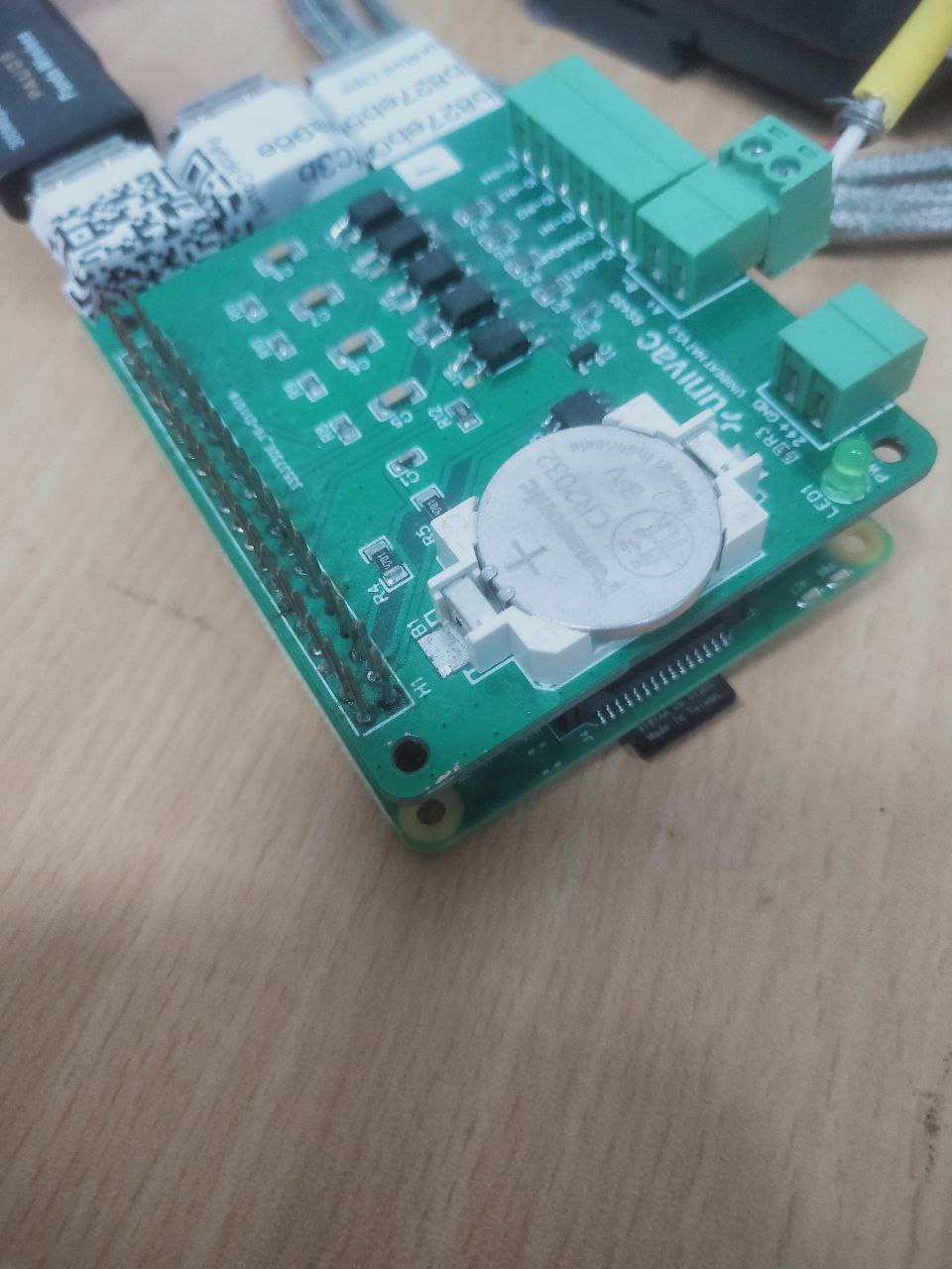
this is a simple Iot board that my team and i customized to enable the raspberrypi to go HAM. we wanted to increase the functionality the raspberrypi could do to support it as an IoT device to communicate the different machines. Some specification include:
1) power connection through a 24V 2) a RTC clock for when there is no power and internet connection 3) modbus TCP/RTU communication 4) input/output digital communication
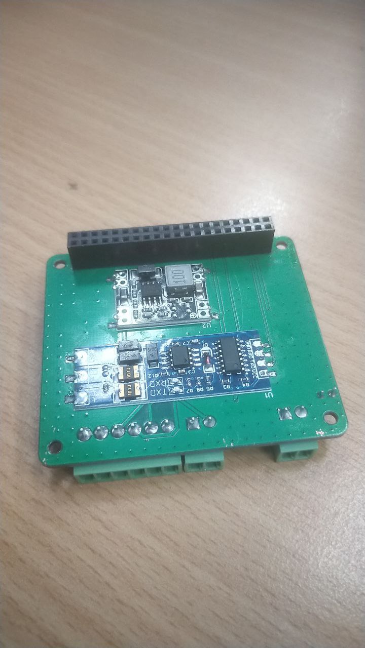
what we came up with was a hybrid IoT board where we still had to solder some parts unfortunately, that would be the 24/5V regulator (pi needs 5V input) and the rs485 to TTL converter.
the board is configured such that we will be used the UART pins to Txd and Rxd infomation, digital inputs will be through a pulldown resistor programically and physically.
power
we used a 24to5V regulartor as we would want to draw power supply from the machines. Since most machines used 24V, we had a plug and play terminal block so that we can just connect it to the machines
hardware clock
the hardware clock is setup to provide the raspberrypi with correct timedate format in the event it cant connect to the NTP server and in the event if it got rebooted
1
2
3
4
5
6
7
8
timedatectl

> NTP service: active

vim /etc/systemd/timesyncd.conf

> NTP=yourntpserver
modbus TCP/RTU
raspberypi comes with a default pin for UART which was where the output of the TTL goes, it receive input from a terminal block and goes through the RS485 connection which was soldered on it.
we used a modbus-serial library to connect to the modbus through “/dev/ttyAMA0”
input/output digital communication
for digital communication, individual pins can be set to receive digital input with a option to pulldown or pullup. debouncing configuations can also be used
making of the board
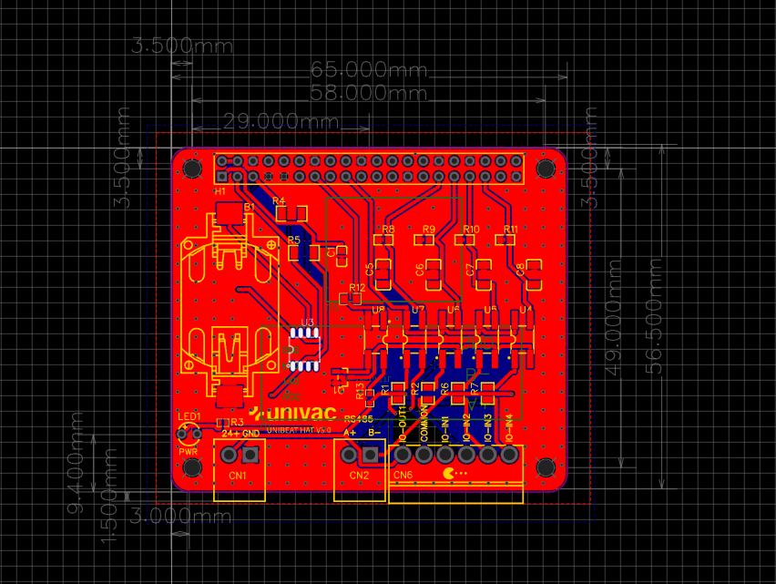
to make the board, we used easyeda to actually design the board and fit all the components together.
easyeda is good because you can manufacture the board after choosing the parts based of their distributor, which is either jlcpcb or lcsc. they also had an auto routing( but we still had to do some manual routing) to help us lay the foundation of the routes such that it conform to board specification. this came with a lot of trial and errors to get it right.
reflection
our final output of the board after being manufactured is as showned. it wasnt as cleanly done and difficult to mass produce since we still had to solder some elements on it. ultimately the power regulators and modbus communication device can be better designed so that there is no need for additional solder by hand, which can lead to bad solder leaks.


